- 您现在的位置:买卖IC网 > Sheet目录3870 > PIC16F648A-I/P (Microchip Technology)IC MCU FLASH 4KX14 EEPROM 18DIP
PIC16F627A/628A/648A
DS40044G-page 110
2009 Microchip Technology Inc.
14.5.1
RB0/INT INTERRUPT
External interrupt on the RB0/INT pin is edge triggered;
either rising if INTEDG bit (OPTION<6>) is set, or
falling, if INTEDG bit is clear. When a valid edge
appears on the RB0/INT pin, the INTF
bit
(INTCON<1>) is set. This interrupt can be disabled by
clearing the INTE control bit (INTCON<4>). The INTF
bit must be cleared in software in the interrupt service
routine before re-enabling this interrupt. The RB0/INT
interrupt can wake-up the processor from Sleep, if the
INTE bit was set prior to going into Sleep. The status of
the GIE bit decides whether or not the processor
branches to the interrupt vector following wake-up. See
for details
on Sleep, and Figure 14-17 for timing of wake-up from
Sleep through RB0/INT interrupt.
14.5.2
TMR0 INTERRUPT
An overflow (FFh
→ 00h) in the TMR0 register will set the
T0IF (INTCON<2>) bit. The interrupt can be enabled/
disabled by setting/clearing T0IE (INTCON<5>) bit. For
operation of the Timer0 module, see Section 6.0
14.5.3
PORTB INTERRUPT
An input change on PORTB <7:4> sets the RBIF
(INTCON<0>) bit. The interrupt can be enabled/disabled
by setting/clearing the RBIE (INTCON<3>) bit. For
operation of PORTB (Section 5.2 “PORTB and TRISB
).
14.5.4
COMPARATOR INTERRUPT
complete description of comparator interrupts.
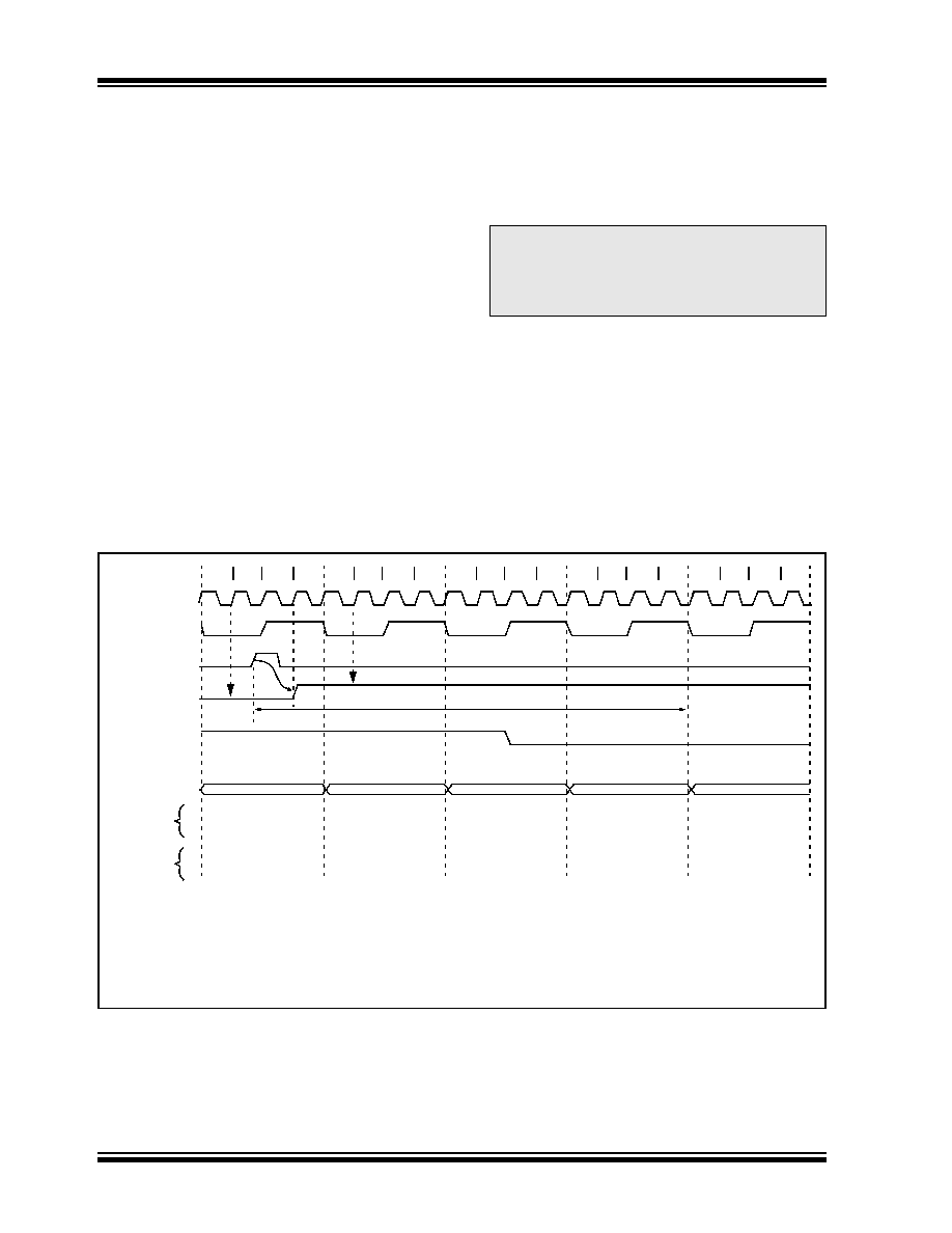
FIGURE 14-15:
INT PIN INTERRUPT TIMING
Note:
If a change on the I/O pin should occur
when the read operation is being executed
(starts during the Q2 cycle and ends before
the start of the Q3 cycle), then the RBIF
interrupt flag may not get set.
Q2
Q1
Q3 Q4
Q2
Q1
Q3 Q4
Q2
Q1
Q3 Q4
Q2
Q1
Q3 Q4
Q2
Q1
Q3 Q4
OSC1
CLKOUT
INT pin
INTF flag
(INTCON<1>)
GIE bit
(INTCON<7>)
Instruction Flow
PC
Instruction
Fetched
Instruction
Executed
Interrupt Latency
PC
PC + 1
0004h
0005h
Inst (0004h)
Inst (0005h)
Dummy Cycle
Inst (PC)
Inst (PC + 1)
Inst (PC - 1)
Inst (0004h)
Dummy Cycle
Inst (PC)
—
Note
1:
INTF flag is sampled here (every Q1).
2:
Asynchronous interrupt latency = 3-4 TCY. Synchronous latency = 3 TCY, where TCY = instruction cycle time.
Latency is the same whether Inst (PC) is a single cycle or a two-cycle instruction.
3:
CLKOUT is available in RC and INTOSC oscillator mode.
4:
For minimum width of INT pulse, refer to AC specs.
5:
INTF is enabled to be set anytime during the Q4-Q1 cycles.
(1)
(4)
(5)
(2)
(3)
发布紧急采购,3分钟左右您将得到回复。
相关PDF资料
PIC18F96J65T-I/PF
IC PIC MCU FLASH 48KX16 100TQFP
PIC16CE623-20/P
IC MCU OTP 512X14 EE COMP 18DIP
PIC24FJ16MC102-I/SO
IC MCU 16BIT 16KB FLASH 28SOIC
DSPIC33FJ16GP102-I/SO
IC DSC 16BIT 16KB 28SOIC
PIC16C57C-04/SO
IC MCU OTP 2KX12 28SOIC
PIC16F627-20/P
IC MCU FLASH 1KX14 COMP 18DIP
PIC24FJ16GA002-I/ML
IC PIC MCU FLASH 16K 28-QFN
PIC16LF627-04/SO
IC MCU FLASH 1KX14 COMP 18SOIC
相关代理商/技术参数
PIC16F648A-I/P
制造商:Microchip Technology Inc 功能描述:IC 8BIT FLASH MCU 16F648 DIP18
PIC16F648A-I/PC06
制造商:Microchip Technology 功能描述:MCU 8-Bit PIC16 PIC RISC 7KB Flash 3.3V/5V 18-Pin PDIP
PIC16F648A-I/SO
功能描述:8位微控制器 -MCU 7KB 256 RAM 16 I/O RoHS:否 制造商:Silicon Labs 核心:8051 处理器系列:C8051F39x 数据总线宽度:8 bit 最大时钟频率:50 MHz 程序存储器大小:16 KB 数据 RAM 大小:1 KB 片上 ADC:Yes 工作电源电压:1.8 V to 3.6 V 工作温度范围:- 40 C to + 105 C 封装 / 箱体:QFN-20 安装风格:SMD/SMT
PIC16F648A-I/SO
制造商:Microchip Technology Inc 功能描述:8BIT FLASH MCU SMD 16F648 SOIC18
PIC16F648A-I/SOC06
制造商:Microchip Technology Inc 功能描述:
PIC16F648A-I/SS
功能描述:8位微控制器 -MCU 7KB 256 RAM 16 I/O RoHS:否 制造商:Silicon Labs 核心:8051 处理器系列:C8051F39x 数据总线宽度:8 bit 最大时钟频率:50 MHz 程序存储器大小:16 KB 数据 RAM 大小:1 KB 片上 ADC:Yes 工作电源电压:1.8 V to 3.6 V 工作温度范围:- 40 C to + 105 C 封装 / 箱体:QFN-20 安装风格:SMD/SMT
PIC16F648A-I/SS
制造商:Microchip Technology Inc 功能描述:8BIT FLASH MCU SMD 16F648 SSOP20
PIC16F648A-I/SSC06
制造商:Microchip Technology Inc 功能描述: